2D automated optical inspection catches the obvious defects. 3D AOI catches the expensive ones. As component packages shrink to 01005 and pitch tightens below 0.3 mm, the defects that fail in the field, lifted leads, insufficient solder, component tilt, head-in-pillow, are exactly the ones a flat 2D camera cannot measure. This guide explains what 3D AOI (3D automated optical inspection) actually does, how it differs from 2D and from in-circuit test, and how Australian SMT manufacturers should choose a system.
3D automated optical inspection uses structured light or laser triangulation to build a true height map of every component and solder joint on a PCB. Where a 2D AOI system sees a top-down photograph, brightness, colour, and 2D position, a 3D AOI system measures the actual Z-axis height of each feature to micron resolution.
That height data is what turns inspection from “is the part present and roughly aligned?” into “is the solder volume correct, is the lead coplanar, is the component tilted?”, the questions that predict field reliability.
| Defect | 2D AOI | 3D AOI |
|---|---|---|
| Missing component | Yes | Yes |
| Wrong component / polarity | Yes | Yes |
| Gross misalignment | Yes | Yes |
| Insufficient / excess solder volume | Limited | Yes (measured) |
| Lifted lead / coplanarity | No | Yes |
| Component tilt | No | Yes |
| Head-in-pillow | No | Yes |
The pattern is clear: 2D handles presence and placement; only 3D handles the solder-joint quality defects that cause latent field failures. For any manufacturer serving aerospace, medical, automotive, or defence, that difference is a customer requirement.
ICT verifies electrical function but requires a bed-of-nails fixture and cannot see a marginal solder joint that passes electrically today and fails thermally in six months. 3D AOI is non-contact, needs no fixture, and inspects 100% of joints, catching the mechanical defects ICT is blind to. The two are complementary, but 3D AOI moves defect detection earlier and cheaper in the line.
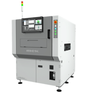
ProfTek supplies the full MEK 3D AOI range across these formats, from the entry-level MEK iSpector JDz inline system to the high-speed selective MEK PowerSpector JSAz, plus the MEK SpectorBOX offline verification workstation and MEK Catch traceability software.
ProfTek is the Australian and New Zealand supplier of the MEK 3D AOI and SMT AOI range. For a system matched to your line speed, board mix, and traceability requirements, contact our engineering team with your production details and we’ll recommend the right MEK configuration with pricing.